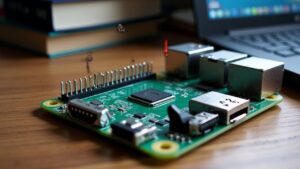
When working with a Raspberry Pi, understanding GPIO (General Purpose Input/Output) pins is key. Raspberry Pi GPIO pins are customizable by software and can be set as inputs to read values or outputs to send signals, represented by high (3.3V) and low (0V) voltages. The Raspberry Pi has a 40-pin header, with two numbering systems: Broadcom chip-specific (BCM) and physical pin numbers (Board). You’ll use libraries like RPi.GPIO or GPIO Zero in Python to configure these pins. Different types of GPIO pins include digital I/O, PWM, and specialized communication pins for protocols like I2C, SPI, and UART. By mastering GPIO, you’ll access a world of project possibilities from smart home automation to robotics, and continuing to explore will reveal even more capabilities.
Key Takeaways
- GPIO Fundamentals: Raspberry Pi GPIO pins are customizable as input or output, using high (3.3V) and low (0V) voltage states.
- Pin Configuration: Pins can be configured using Broadcom (BCM) or physical (Board) numbering systems, with two modes: GPIO.BCM and GPIO.BOARD.
- Setup and Coding: Install the GPIO package, use Python IDE with root privileges, and include ‘GPIO.cleanup()’ to manage resources and prevent hardware issues.
- Types of Pins: Digital I/O, PWM, and specialized communication pins (I2C, SPI, UART) serve various applications like control, sensing, and serial communication.
- Limitations and Protections: Ensure proper voltage levels, use protection components like diodes, and follow good circuit design to avoid damaging GPIO pins.
What Is GPIO?
When working with embedded systems or microcontrollers, you’ll often encounter the term “GPIO,” which stands for General Purpose Input/Output.
GPIO fundamentals revolve around the concept of a generic pin on an integrated circuit or electronic circuit board that doesn’t have a specific function and is customizable by software. This flexibility allows you to configure the pin as either an input or an output, making it highly versatile in various applications.
In terms of configuration and control, you can adjust the behavior of a Raspberry Pi GPIO pin at runtime, enabling or disabling it as needed. Input values are readable, with 1 representing high voltage and 0 representing low voltage, while output can be set to HIGH (typically 3.3 volts) or LOW (no voltage). Pull-up or pull-down resistors can also set the default status of the GPIO pin.
For example, Raspberry Pi GPIO pins may operate at different voltage levels such as 3.3V or 5V, and incorrect voltage can damage input GPIO lines.
Understanding these basics is essential for optimizing GPIO performance and troubleshooting potential issues. However, it’s important to be aware of GPIO limitations, such as signal integrity protections provided by components like protection diodes and TTL Schmitt triggers. Additionally, GPIO pins are commonly found on multifunction chips, including power managers and audio/video cards.
Understanding these basics is essential for optimizing GPIO performance and troubleshooting potential issues. However, it’s important to be aware of GPIO limitations, such as signal integrity protections provided by components like protection diodes and TTL Schmitt triggers.
GPIO Pin Layout
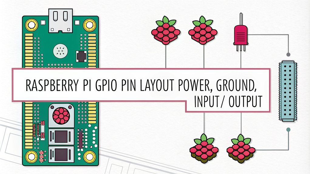
When working with the Raspberry Pi, you need to understand the GPIO pin layout, which includes the pin header structure and the different numbering schemes.
The GPIO header has expanded from 26 pins to 40 pins over time, maintaining the original pinout. This layout includes various types of pins such as power, ground, input, and output.
You’ll encounter two main numbering systems: the Broadcom chip-specific pin numbers and the P1 physical pin numbers, each with its own set of references and special functions.
| Pin | Name | Type | Description |
|---|---|---|---|
| 1 | 3.3V | Power | 3.3V power supply. |
| 2 | 5V | Power | 5V power supply. |
| 3 | GPIO2 (SDA1) | I2C, GPIO | Data line for I2C (SDA). |
| 4 | 5V | Power | 5V power supply. |
| 5 | GPIO3 (SCL1) | I2C, GPIO | Clock line for I2C (SCL). |
| 6 | GND | Ground | Ground. |
| 7 | GPIO4 | GPIO, PWM | General-purpose pin, can be used as PWM. |
| 8 | GPIO14 (TXD0) | UART, GPIO | UART Transmit (TX). |
| 9 | GND | Ground | Ground. |
| 10 | GPIO15 (RXD0) | UART, GPIO | UART Receive (RX). |
| 11 | GPIO17 | GPIO | General-purpose pin. |
| 12 | GPIO18 | GPIO, PWM | General-purpose pin, supports PWM. |
| 13 | GPIO27 | GPIO | General-purpose pin. |
| 14 | GND | Ground | Ground. |
| 15 | GPIO22 | GPIO | General-purpose pin. |
| 16 | GPIO23 | GPIO | General-purpose pin. |
| 17 | 3.3V | Power | 3.3V power supply. |
| 18 | GPIO24 | GPIO | General-purpose pin. |
| 19 | GPIO10 (MOSI) | SPI, GPIO | SPI MOSI (Master Out Slave In). |
| 20 | GND | Ground | Ground. |
| 21 | GPIO9 (MISO) | SPI, GPIO | SPI MISO (Master In Slave Out). |
| 22 | GPIO25 | GPIO | General-purpose pin. |
| 23 | GPIO11 (SCLK) | SPI, GPIO | SPI Clock. |
| 24 | GPIO8 (CE0) | SPI, GPIO | SPI Chip Enable 0. |
| 25 | GND | Ground | Ground. |
| 26 | GPIO7 (CE1) | SPI, GPIO | SPI Chip Enable 1. |
| 27 | GPIO0 (ID_SD) | I2C EEPROM, GPIO | ID EEPROM (I2C Data). |
| 28 | GPIO1 (ID_SC) | I2C EEPROM, GPIO | ID EEPROM (I2C Clock). |
| 29 | GPIO5 | GPIO | General-purpose pin. |
| 30 | GND | Ground | Ground. |
| 31 | GPIO6 | GPIO | General-purpose pin. |
| 32 | GPIO12 | GPIO, PWM | General-purpose pin, supports PWM. |
| 33 | GPIO13 | GPIO, PWM | General-purpose pin, supports PWM. |
| 34 | GND | Ground | Ground. |
| 35 | GPIO19 | GPIO, PWM | General-purpose pin, supports PWM. |
| 36 | GPIO16 | GPIO | General-purpose pin. |
| 37 | GPIO26 | GPIO | General-purpose pin. |
| 38 | GPIO20 | GPIO, PWM | General-purpose pin, supports PWM. |
| 39 | GND | Ground | Ground. |
| 40 | GPIO21 | GPIO, PWM | General-purpose pin, supports PWM. |
Pin Header Structure
The Raspberry Pi GPIO pin header is an essential component, consisting of 40 pins that are sequentially numbered from Pin 1 at the top left to Pin 40 at the bottom right. This layout remains consistent across Raspberry Pi 3 and 4 models, guaranteeing compatibility and ease of use for various projects.
The pin header structure is designed to facilitate multiple types of connections and functionalities. Power pins, such as the 5V pins (Pin 2, 4) and 3.3V pins (Pin 1, 17), provide the necessary voltage for your projects. Multiple ground pins (Pin 6, 9, 14, 20, 25, 30, 34, 39) are available to complete electrical circuits efficiently.
Specialized pins support different communication protocols like I2C (SDA, SCL), SPI (MOSI, MISO, CLK), and UART (TXD, RXD), enhancing the device’s versatility. Additionally, some GPIO pins support Pulse Width Modulation (PWM) for analog output. The color-coding in diagrams helps in easy identification of specific pin functions.
Understanding the pin header structure is essential for building and testing circuits, integrating hardware components like sensors and actuators, and leveraging the full potential of the Raspberry Pi in your innovative projects. It is also crucial to remember that each pin operates at 3.3V to avoid damage. For example, configuring a GPIO pin as an output requires setting it to high or low using a Python script, such as setting GPIO 18 to high for one second.
This structured approach guarantees that you can effectively manage and utilize each pin according to your project’s requirements.
Board and BCM Numbering (Raspberry Pi GPIO Pin Layout)
Understanding the Raspberry Pi GPIO pin layout involves grasping two distinct numbering systems: Board and BCM. These systems are essential for accurately accessing and utilizing the GPIO pins in your projects.
Board Numbering
The Board numbering system references the physical location of pins on the board. It counts from 1 to 40 for the 40-pin header, starting from the top left. This system simplifies pin identification, especially for beginners, as it doesn’t change between different Raspberry Pi models.
In programming, you use ‘GPIO.BOARD’ mode to work with this numbering scheme. Ensuring correct pin identification is crucial because incorrect connections can lead to potential bricking of the Raspberry Pi. For example, when connecting devices like LEDs or sensors, using the correct physical pin numbers helps in avoiding short circuits.
BCM Numbering
The BCM (Broadcom Chip-Specific) numbering system is based on the internal pin numbering of the Broadcom chip. This system is used by low-level software and can change between different Raspberry Pi models, such as between Rev 1 and later models.
To use this system in programming, you must declare ‘GPIO.BCM’ mode.
Key Differences
- Pin Mapping:
- Physical pin 7 corresponds to internal GPIO 4 in BCM mode.
- Different mappings for different models.
- BCM numbers are specific to the chip, while board numbers are physical.
- Programming Modes:
- You must declare whether you’re using ‘GPIO.BOARD’ or ‘GPIO.BCM’ mode in your program.
- Choosing the right mode depends on your project’s needs and your preference.
- Beginner Tips and Advanced Usage:
- For beginners, ‘GPIO.BOARD’ mode is often easier to understand.
- For advanced users, ‘GPIO.BCM’ mode is more common due to its use in low-level software. Understanding these modes is particularly important when working with multiple interfaces like PWM, I2C, and SPI.
When working with Raspberry Pi GPIO pins, properly declaring the numbering scheme avoids confusion and errors in GPIO access. Some libraries and scripts may also require a specific mode, so it’s important to choose the right one for your project. Additionally, understanding power limitations and connected devices is necessary to prevent damage to your setup power limitations.
Types of GPIO Pins
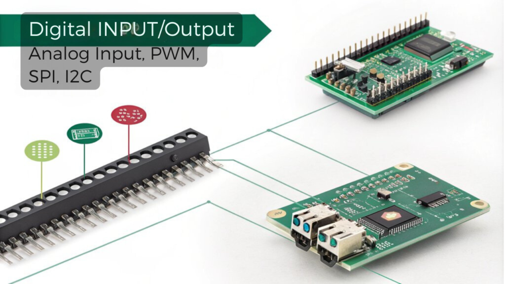
Raspberry Pi GPIO pins are categorized into several types, each serving distinct functions that enable a wide range of applications. One of the most common types is the Digital I/O Pins, which can be configured as either input or output pins. These pins are fundamental for basic on/off control of devices such as LEDs and relays, and they can handle digital data from sensors and switches.
For more nuanced control, PWM (Pulse Width Modulation) Pins are used to adjust the brightness of LEDs, the speed of motors, or the position of servos by modifying the duty cycle of the PWM signal. While hardware PWM is available on specific pins, software PWM can be implemented on all GPIO pins.
ADC (Analog to Digital Converter) Pins, though not standard on most Raspberry Pi models but available on some like the Raspberry Pi Pico, allow you to read analog signals from sensors and convert them into digital values. This is critical for interfacing with analog devices like temperature or light sensors.
Communication Protocol Pins such as I2C, SPI, and UART enable communication with various peripherals and devices. I2C uses two pins (SDA and SCL), SPI involves MISO, MOSI, and serial clock pins, while UART uses TX and RX pins for serial communication. These protocols are essential for sensor integration and hardware interfaces in various GPIO applications.
Understanding these pin configurations is key to harnessing the full potential of your Raspberry Pi projects, especially when connecting to various projects like smart mirrors, weather stations, or asset trackers.
Configuring GPIO Pins
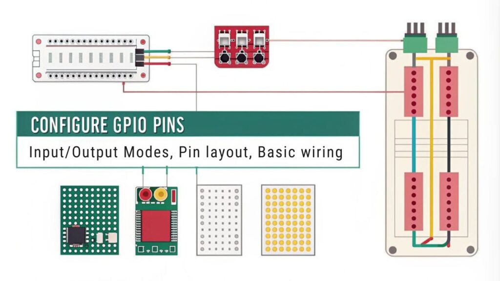
To configure GPIO pins on your Raspberry Pi, you need to set up your environment and confirm you have the necessary tools and libraries installed. Start by updating your operating system with ‘sudo apt update’ and ‘sudo apt upgrade’ to confirm you have the latest version of Raspberry Pi OS.
If the GPIO package isn’t already installed, run ‘sudo apt install rpi.gpio‘ to install it.
Next, open the Terminal on your Raspberry Pi and open the Python IDE with root privileges using ‘sudo idle3 &’. This will allow you to write and execute scripts for GPIO pin control.
It is important to remember that GPIO pins operate at 3.3V, so ensure compatibility of components to avoid damage.
Here are some key steps for configuring Raspberry Pi GPIO pins:
- Import Libraries: Import the ‘RPi.GPIO’ and ‘time’ libraries in your Python script to handle GPIO and timing functions.
- Set GPIO Mode: Use ‘GPIO.setmode(GPIO.BCM)’ or ‘GPIO.setmode(GPIO.BOARD)’ to set the GPIO mode. You can also disable warnings with ‘GPIO.setwarnings(False)’.
- Assign Pin Variables: Assign specific GPIO pins to variables, such as ‘led = 4’ and ‘button = 14’.
To control the pins, use ‘GPIO.setup(led, GPIO.OUT)’ to set a pin as an output and ‘GPIO.setup(button, GPIO.IN, GPIO.PUD_UP)’ to set a pin as an input with a pull-up resistor.
Always include ‘GPIO.cleanup()’ at the end of your script to clean up the GPIO settings and free the pins for other projects. This confirms proper resource management and prevents potential hardware issues.
Applications of GPIO Pins
When you explore the world of Raspberry Pi, the versatility of GPIO pins becomes evident through their numerous applications in control and automation, sensing and monitoring, communication, and project prototyping.
In control and automation, you can use GPIO pins to turn LEDs, motors, and other actuators on or off. PWM (Pulse Width Modulation) allows for precise control over motors and LEDs. You can also manage relays to switch higher voltage devices, automating home appliances and lighting systems. For example, you can create automation examples like smart home systems where lights and appliances are controlled remotely.
For sensing and monitoring, GPIO pins enable data collection from various sensor modules such as temperature, humidity, and pressure sensors using I2C and SPI protocols. You can monitor switches and buttons for input and collect data from cameras and other vision sensors. This is significant for setting up monitoring systems like weather stations that track environmental changes.
In communication, GPIO pins facilitate serial communication via UART pins and enable communication with other microcontrollers and devices using SPI and I2C protocols. You can also send and receive data between the Raspberry Pi and other devices, including Bluetooth and Wi-Fi modules, as well as interface with GPS and GSM modules for location and cellular connectivity. Ensuring proper connections is crucial, as a 10K resistor can mitigate floating input issues.
When it comes to project ideas and prototyping, GPIO pins are essential for integrating various sensors and actuators. The Grove Base Hat simplifies prototyping with over 300+ sensors and modules. This makes it ideal for developing IoT projects, building interactive installations, and designing robotic systems and autonomous vehicles.
With these capabilities, you can bring innovative project ideas to life efficiently.
Coding for GPIO Pins
When coding for GPIO pins on your Raspberry Pi, you’ll often find Python to be the most straightforward option due to its simplicity and extensive libraries like RPi.GPIO and GPIO Zero.
These libraries allow you to easily import necessary modules, set up pin modes, and control the state of your Raspberry Pi GPIO pins with commands like ‘GPIO.setup’ and ‘GPIO.output’. For example, you can use the ‘GPIO.setmode()’ function to specify the numbering system, such as Broadcom chip-specific or physical pin layout.
Additionally, the GPIO Zero library is particularly user-friendly, making it a great choice for beginners due to its simple syntax.
For more advanced control, you might also consider using Node.js modules, which can provide additional functionality and integration with other systems.
Coding With Python (Coding for GPIO Pins)
Coding with Python is a fundamental step in utilizing the GPIO pins of your Raspberry Pi. To get started, you need to import the appropriate GPIO library. You can use either ‘import RPi.GPIO as GPIO’ for more detailed control or ‘from gpiozero import Button’ for simpler interactions.
Setting Up Your Environment
- Importing Libraries: Import the necessary GPIO library to interact with your Raspberry Pi’s pins.
- Selecting Pin Numbering: Choose between ‘GPIO.BCM’ for Broadcom chip-specific pin numbers or ‘GPIO.BOARD’ for physical board pin numbers.
- Disabling Warnings: Use ‘GPIO.setwarnings(False)’ to avoid unnecessary warning messages.
- Ensure you use ‘GPIO.cleanup()’ to clean up GPIO resources after script execution to prevent resource conflicts.
To configure a pin, use ‘GPIO.setup(pin, GPIO.IN)’ for input or ‘GPIO.setup(pin, GPIO.OUT)’ for output. For output pins, you can initialize them with a high state using ‘GPIO.setup(pin, GPIO.OUT, initial=GPIO.HIGH)’. Ensure you understand the 40-pin header layout to correctly identify and use each pin.
Configuring and Interacting with Pins
To configure a pin, use ‘GPIO.setup(pin, GPIO.IN)’ for input or ‘GPIO.setup(pin, GPIO.OUT)’ for output. For output pins, you can initialize them with a high state using ‘GPIO.setup(pin, GPIO.OUT, initial=GPIO.HIGH)’.
Key Considerations
- Button Interactions: Use ‘if button.is_pressed:’ with ‘gpiozero’ or ‘if GPIO.input(pin) == 0:’ with ‘RPi.GPIO’ to detect button presses.
- Pin Monitoring: Employ ‘while True:’ loops to continuously monitor and react to GPIO pin states.
- Safety Precautions: Be aware of power limitations and the risk of damaging your Raspberry Pi when working with PWM output, which is limited to pin 18.
When coding, refer to Raspberry Pi GPIO pinout diagrams to verify correct pin usage and follow efficient coding practices to avoid common issues.
Debugging techniques are essential; use strategies like checking pin configurations and power supply to identify and solve errors effectively.
Using Node.js Modules
To start coding for GPIO pins using Node.js, you first need to set up your environment with the necessary packages and libraries. Use the ‘apt’ package manager to install Node.js and the required libraries such as ‘libgpiod’ and ‘libgpiod-dev’ for GPIO access on your Raspberry Pi 5. Confirm you install an ARM-compatible version of Node.js tailored to your specific Raspberry Pi model.
When selecting Node.js modules, consider the features you need. For basic operations, ‘rpi-gpio’ and ‘onoff’ are simple and easy to use. However, if you require advanced features like PWM, SPI, or I²C, ‘pigpio’ is a better choice. ‘node-libgpiod’ supports event-driven programming and is particularly useful for handling button presses or other input events.
In terms of performance, ‘rpio’ stands out as considerably faster than modules using the ‘/sys’ interface, offering up to 1000x better performance. Note that due to compatibility issues, many existing libraries fail to function on the RPi 5, so choosing the right library is crucial.
When coding, define GPIO pin numbers based on your Raspberry Pi model’s pinout and use library functions to set up pins as inputs or outputs. Use event listeners to handle changes in GPIO pin states, and confirm you follow the correct pin numbering scheme depending on the library you’re using.
Library dependencies such as ‘libnode-dev’ may also be required for development purposes. Always confirm compatibility between your Node.js version and Raspberry Pi model to avoid any issues.
Frequently Asked Questions
How Do I Protect My Raspberry Pi From GPIO Pin Damage?
To protect your Raspberry Pi’s GPIO pins, use clamp diodes or Schottky diodes for voltage protection, limiting voltage to 3.3V + 0.7V. Add resistors to limit current draw and consider opto-isolators for total isolation and noise protection.
Can I Use GPIO Pins to Power External Devices Directly?
You can use the 5V power pins on the GPIO header to power external devices, but not high-current devices. GPIO pin limitations mean they can’t handle servo or stepper motors without an external power source. Verify voltage compatibility and common grounding to avoid damage.
What Is the Maximum Current a GPIO Pin Can Handle?
The maximum current a GPIO pin can handle is 16mA, ensuring safe voltage levels within the GPIO pin specifications to prevent damage. Exceeding this limit can potentially harm the pin.
How Do I Troubleshoot Common Issues With GPIO Pins?
To troubleshoot GPIO pin issues, check the GPIO pin configurations for correct mode settings and pull-up/pull-down resistors. Verify wiring and connections, guarantee no pin damage, and update the RPi.GPIO library. Monitor script logic and OS compatibility, considering GPIO pin limitations.
Are There Any Specific Tools Needed to Work With GPIO Pins?
To work with GPIO pins, you’ll need a breakout kit, ribbon cable, breadboard, and jumper wires for prototyping. Utilize GPIO programming libraries like RPi.GPIO or GPIO Zero for configuring GPIO pin configurations.
Conclusion
As you wrap up your journey through the world of Raspberry Pi GPIO pins, imagine a simple LED flickering to life beside a complex robotic arm moving with precision. This contrast highlights the versatility of GPIO pins: from basic lighting projects to intricate automation systems. With each pin configured and coded, you bridge the gap between idea and reality, transforming mere concepts into functioning marvels of technology.

I am a retired software engineer with experience in a multitude of areas including managing AWS and VMWare development environments. I bought a relative a mini-PC a year ago and have become passionate about the technology and its potential to change how we deploy software.

