How can using Python for SPI Programming Help Your Next Project?
You’ll find SPI communication essential when interfacing with numerous sensors, displays, and memory devices on your Raspberry Pi projects. Python for SPI programming offers a straightforward approach to controlling these devices through the spidev library, making hardware communication accessible even without deep electronics knowledge. Once you understand the basics of bus configuration and data transfer protocols, you can build sophisticated systems with multiple SPI peripherals operating simultaneously—a capability that will dramatically expand your project possibilities.
Key Takeaways
- Enable SPI on Raspberry Pi using `sudo raspi-config`, then install the Python `spidev` library with `pip install spidev`.
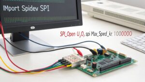
- Initialize SPI communication with `import spidev; spi = spidev.SpiDev(); spi.open(0, 0)` where 0 is the bus and 0 is the device.
- Configure SPI parameters like speed with `spi.max_speed_hz = 1000000` and mode with `spi.mode = 0` to match your device requirements.
- Transfer data using `spi.xfer2([values])` for sending/receiving data simultaneously, or `spi.writebytes([values])` for sending only.
- Manage multiple SPI devices by using different chip select pins (CE0, CE1) and creating separate SpiDev instances for each device.
Understanding the SPI Protocol Fundamentals
Serial Peripheral Interface (SPI) forms the backbone of high-speed device communication in embedded systems like Raspberry Pi. This synchronous protocol operates on a Master-Slave architecture where your Raspberry Pi typically functions as the master controlling multiple peripheral slaves.
SPI’s power lies in its Full-Duplex capability, allowing simultaneous bidirectional data transfer through dedicated MOSI (master out, slave in) and MISO (master in, slave out) lines. The Clock Signal synchronizes Data Direction between devices, enhancing Communication Efficiency. Each slave device requires an active low CS signal from the master to initiate communication. Unlike more complex protocols, SPI uses simpler signals that make it ideal for microcontroller communication with sensors and displays.
SPI delivers unmatched speed through simultaneous data exchange, with precision timing that maximizes communication throughput.
You’ll need to configure one of four SPI Modes (0-3) based on clock polarity and phase requirements of your target device. On Raspberry Pi, SPI is available through specific GPIO pins in the 40-pin header, which you’ll need to reference using either BCM or Board numbering systems.
Different Transaction Types support various data exchange patterns across Protocol Variants, including standard 4-wire and simplified 3-wire configurations. Understanding these fundamentals guarantees you’ll implement robust SPI communication in your Python projects.
Enabling SPI on Your Raspberry Pi
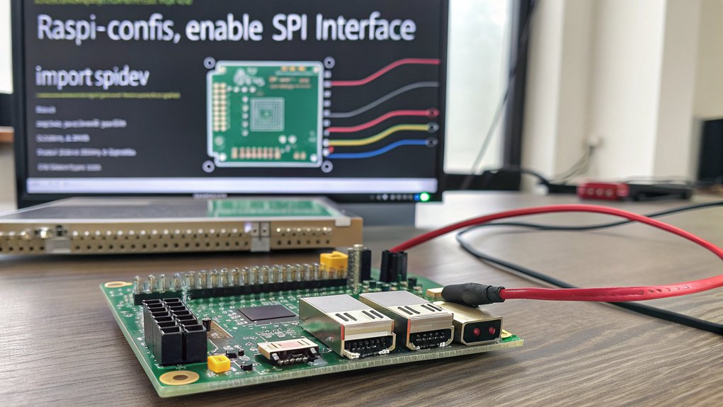
Before you can leverage Python for SPI communication capabilities on your Raspberry Pi, you’ll need to explicitly activate the interface since it’s disabled by default in the system’s kernel. The simplest method is using the built-in configuration tool:
- Open terminal and run `sudo raspi-config`
- Navigate to “Interfacing Options” and select “SPI”
- Choose “ to enable the interface
- Reboot your Pi for changes to take effect
Verify your configuration with `lsmod | grep spi` to confirm the spi-bcm2835 module is loaded. You can also check if SPI is properly enabled by running ls /dev/spi. Common issues include device conflicts and improper kernel module loading. Troubleshooting tips: check `/boot/config.txt` for conflicting configurations, verify you’ve rebooted after enabling SPI, and use `gpio readall` to check GPIO pin status. For advanced users, manual configuration without raspi-config is possible but typically still requires rebooting. Alternatively, you can enable SPI directly from the command line with sudo dtparam spi=on.
Installing Required Libraries when using Python for SPI
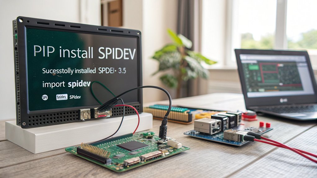
To install python for SPI support for your Raspberry Pi, you’ll need the `spidev` package which provides Python bindings for SPI communication.
Install it by running `sudo pip install spidev` or `sudo apt-get install python3-spidev` depending on your preferred installation method.
Before proceeding with your SPI programming, check that all dependencies are installed by running a simple test script that imports the library and attempts to open an SPI connection.
The SPI functionality may vary between different Raspbian versions, so be aware that code working in older versions might need adjustments when using newer Raspbian distributions.
Remember that SPI must be enabled in the Pi’s configuration since it is off by default and requires activation through either the Desktop GUI or raspi-config in terminal.
Install SpiDev Package
Installing the SpiDev package represents an essential first step in working with SPI communication on your Raspberry Pi. You’ll need Python installed (either version 2 or 3) before proceeding with the installation. If you encounter errors during installation, you may need to install Python-dev package using apt-get. The package enables direct kernel access to SPI devices through the Linux spidev driver.
| Installation Method | Common Issues |
|---|---|
| PyPI Download | Version compatibility |
| `setup.py` | Python dependency conflicts |
| APT Package | Limited distribution support |
| Manual Source | Requires compilation skills |
| Git Repository | Needs additional git setup |
To install SpiDev dependencies, first enable the SPI driver by editing `/etc/modprobe.d/raspi-blacklist.conf`. Download the package from PyPI, extract it using `tar -xvf spidev-3.4.tar.gz`, then install with `sudo python3 setup.py install`. When troubleshooting installation issues, verify your Python version compatibility and confirm you’ve rebooted after enabling the SPI driver.
Library Dependencies Check
Properly functioning SPI communication depends heavily on having the right Python libraries installed on your Raspberry Pi system. The `spidev` package is essential for handling SPI interfaces, unlike `smbus` which serves I2C protocols only.
Ensure library compatibility by running `apt-get update` followed by installation of the necessary packages. SPI interfaces aren’t enabled by default, requiring configuration through `raspi-config` tools and a system reboot. This step is vital for device communication and prevents common installation issues. Remember to setup your Raspberry Pi in a master-slave configuration for successful SPI operation.
For error management, verify your SPI interfaces (`spidev0.0`, `spidev0.1`) are properly configured with correct mode and frequency settings. You may need to adjust the bit order settings when troubleshooting display issues with OLED screens.
While `spidev` works primarily on Linux systems, understanding these principles supports cross-platform development when implementing SPI communication across different hardware environments. If you’re using Raspberry Pi OS (formerly Raspbian), take advantage of its package management system to easily update and maintain your SPI-related libraries. Consider using the Raspberry Pi 4 model with 8GB RAM variant for more complex SPI programming tasks that require significant memory resources.
Configuring SPI Bus Parameters in Python

You’ll need to configure key SPI bus parameters after initializing your SpiDev object to guarantee proper communication with your target device.
Set the bus speed with `spi.max_speed_hz = 1000000` to match your device’s capabilities, and choose the appropriate SPI mode (0-3) using `spi.mode` to control clock polarity and phase relationships.
When working with multiple SPI devices, manage them by creating separate SpiDev instances with unique chip select values like `spi1 = spidev.SpiDev(0, 0)` and `spi2 = spidev.SpiDev(0, 1)`. For GPIO control, you’ll need to access specific register addresses to configure pin direction and states. This interface supports reading from analog sensors such as the MCP3002 ADC, which can be used for analog voltage measurement in your Raspberry Pi projects.
Bus Speed Configuration
When working with SPI communication on the Raspberry Pi, properly configuring the bus speed is essential for reliable data transfer. You’ll set this using the spidev library by assigning the max_speed_hz attribute after opening your SPI device:
“`python
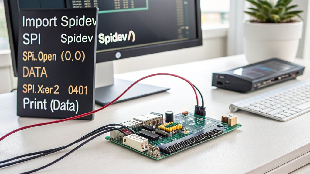
import spidev
spi = spidev.SpiDev()
spi.open(0, 0)
spi.max_speed_hz = 1000000 # 1 MHz
“`
| Speed Range | Limitations | Best Practices |
|---|---|---|
| 0.5-32 MHz | Device specs | Start low, test |
| Hardware dependent | Bus capacitance | Keep wiring short |
| Core clock divisor | EMI environment | Verify in deployment |
Always check your slave device’s datasheet for maximum supported speeds. Begin with conservative speeds and gradually increase while monitoring signal integrity. If you encounter communication errors or lockups, reduce your bus speed—wiring quality considerably impacts performance optimization at higher frequencies. Unlike I2C, SPI does not have standard speed options that serve as common defaults across devices. This approach works especially well when controlling LPD8806 RGB strips with the Raspberry Pi.
Mode and Polarity Settings
SPI communication requires precise configuration of mode and polarity settings to confirm proper data exchange between devices. The four SPI modes (0-3) are defined by combinations of CPOL (clock polarity) and CPHA (clock phase) values, which determine clock settings and data capture timing.
In Python, you can configure these parameters using the spidev library:
“`python
import spidev
spi = spidev.SpiDev()
spi.open(0, 0) # bus 0, device 0
spi.mode = 1 # Set to Mode 1 (CPOL=0, CPHA=1)
“`
Mode compatibility is critical for device synchronization—always check your device’s datasheet for supported modes.
The phase impact affects when data is sampled, while clock polarity determines the idle state. Most devices use Mode 0 or 1, but you should verify requirements to confirm reliable communication.
Multi-Device Communication Management
Beyond mode configurations, effectively managing multiple SPI devices on a single Raspberry Pi requires careful bus parameter configuration in Python. When implementing multi-device setups, proper device selection through unique chip select lines (CE0, CE1) is essential for addressing each component independently.
Configure each device’s speed limitations using `spi.max_speed_hz`, adjusting from kHz to MHz based on your hardware capabilities.
For practical chip management, initialize separate SPI instances:
“`python
import spidev
spi0 = spidev.SpiDev()
spi1 = spidev.SpiDev()
spi0.open(0, 0) # First device on CE0
spi1.open(0, 1) # Second device on CE1
“`
Implement efficient data transfer methods using `spi.xfer()` for simultaneous transmission and reception.
Guarantee proper data formatting based on each device’s protocol requirements and addressing techniques to maintain communication integrity across all connected components.
Troubleshooting communication issues is easier when you encourage iterative programming techniques that help identify and resolve errors systematically.
Connecting SPI Devices to Raspberry Pi GPIO Pins
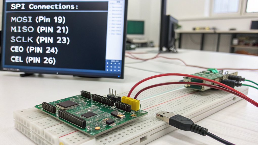
For successful SPI communication, you’ll need to properly connect your peripheral devices to the Raspberry Pi’s GPIO pins following specific pin assignments. Connect MOSI, MISO, SCLK, and CS pins directly to their corresponding GPIO pins—SPI0 uses pins 7-11, while SPI1 uses pins 16-21.
When connecting multiple devices, they can share MOSI, MISO, and SCLK lines, but each device requires a dedicated CS pin for chip select management. Confirm voltage compatibility—Raspberry Pi GPIOs operate at 3.3V, so use level shifters for 5V devices to prevent damage. Unlike the Arduino which operates on an 8-bit architecture, the Raspberry Pi’s 64-bit architecture allows for more sophisticated SPI device interactions. Regular sensor calibration is essential for maintaining measurement accuracy over extended periods of monitoring.
Follow wiring best practices: maintain a common ground connection, keep wires short to minimize interference, and disconnect power when modifying connections. If you encounter connection issues, consider checking Pinout.xyz resource for accurate GPIO pin diagrams and troubleshooting information. Remember that pin numbering can be confusing, so verify whether you’re using GPIO/BCM numbers or physical position numbers as described in Pinout’s documentation.
For multiple SPI buses, enable SPI1 by adding `dtoverlay=spi1-3cs` to `/boot/config.txt`.
Writing Your First Python SPI Communication Script
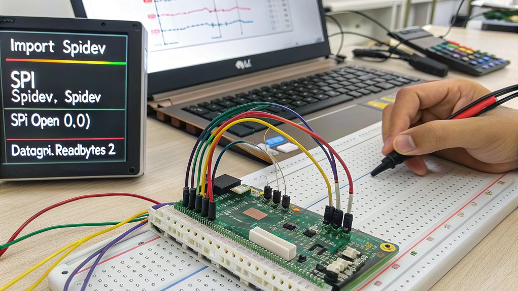
Now that your Raspberry Pi’s SPI interface is properly connected, let’s immerse ourselves in creating your first Python script for SPI communication. Begin by importing the spidev library and initializing your device with proper SPI device selection parameters.
| Operation | Code Example | Purpose | |
|---|---|---|---|
| Initialize | `spi = spidev.SpiDev(0, 0)` | Select SPI bus 0, CS0 | |
| Configure | `spi.max_speed_hz = 1000000` | Set 1MHz clock | |
| Transfer | `result = spi.xfer2([0x01, 0x02])` | Send/receive data | |
| Parse | `value = ((result[0] & 0x03) << 8) \ | result[1]` | Data format parsing |
| Cleanup | `spi.close()` | Release resources |
For application-specific protocols, implement proper bit manipulation techniques when constructing command bytes. Remember that SPI offers full duplex communication allowing simultaneous data transmission in both directions. Always maintain proper GPIO state through resource management practices by closing your SPI connection when finished.
Reading Data From SPI Sensors With Python
Having established the fundamentals of Python SPI communication, let’s examine how to read actual data from SPI sensors.
To acquire meaningful sensor data, you’ll need to implement proper conversion methods based on sensor-specific data formats and calibration techniques.
- Use `spi.xfer2([command_byte])` to send commands and receive responses in a single transaction, essential for real-time monitoring.
- Convert raw bytes to meaningful values using bitwise operations or struct unpacking according to datasheet specifications.
- Apply calibration formulas to transform digital readings into physical units (temperature, pressure, etc.).
- Implement multi-sensor management by controlling chip select lines programmatically when cycling through different devices.
Remember to consult your sensor’s datasheet to understand timing requirements and register structures before attempting data acquisition. When working with ADC devices like MCP3008, ensure you’re specifying valid input channels as attempting to read from non-existent channels will result in errors. When troubleshooting communication issues, you might need to monitor SPI lines using tools like pigpio library to observe signal integrity and clock behavior. For advanced audio applications, consider using the I2S interface which provides higher quality digital audio transmission between your sensors and the Raspberry Pi.
Sending Commands to SPI Display Modules
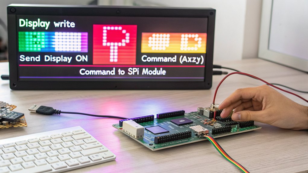
When working with SPI display modules, you’ll need to understand the specific command protocols required by your hardware, which typically involve setting command bits followed by data bytes in a precise sequence.
You can optimize animation performance by implementing buffer handling techniques that minimize the frequency of SPI transmissions and update only changed portions of the display.
These buffer techniques often involve maintaining a local memory representation of the display content, comparing new frames against the previous state, and sending only differential updates through your SPI connection.
Display Command Protocols
To effectively communicate with SPI display modules, you’ll need to understand the specific command protocols they use. Each display module implements a unique command structure requiring precise byte formatting for successful operation. The `spidev` module handles the low-level data transfer while you focus on constructing commands that align with your display’s protocols.
- Commands typically include a start bit, device select bits, and data bits arranged in a specific order.
- Use bitwise operations to construct command bytes according to your module’s documentation.
- Implement the `xfer2()` method for full duplex communication, allowing simultaneous data transmission and reception.
- Validate command execution with proper error detection to guarantee data synchronization.
Command timing is critical—sending commands too quickly or improperly formatted can result in display malfunctions or data corruption. Leveraging GPIO pins capabilities can enhance your SPI communication by providing additional control signals when interfacing with complex display modules.
Animation Buffer Handling
Implementing efficient animation buffer handling forms the foundation of smooth display updates when working with SPI displays on Raspberry Pi. By creating a frame buffer in RAM, you’ll achieve superior animation smoothness while minimizing SPI overhead.
Instead of sending individual pixel updates, optimize your buffer to transmit complete frames, ensuring predictable frame rates regardless of content complexity. For memory allocation, create a byte array that accommodates your display’s resolution and 16-bit color depth requirements.
Boost buffer efficiency through incremental updates—only refresh changed portions of the display when possible. Frame optimization techniques include selecting appropriate SPI modes (typically Mode 0 or 3) and adjusting buffer size dynamically based on display resolution. Using a frame buffered solution allows for implementing a wider range of applications with your SPI LCD panels.
For complex animations, batch processing through buffers substantially outperforms direct pixel drawing, especially when working within hardware-constrained SPI clock speeds.
Debugging Common SPI Communication Issues
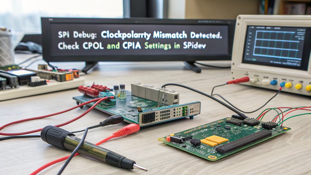
Debugging SPI communication issues requires a systematic approach to identify and resolve configuration, library, hardware, and data transmission problems.
When troubleshooting your Raspberry Pi SPI implementation, focus on error identification and configuration validation to guarantee signal integrity and communication stability.
- Verify your SPI mode settings (CPOL/CPHA) match your device’s requirements—incompatible modes are a leading cause of transmission failures.
- Check for unsupported flags like `spi.lsbfirst` which aren’t compatible with Raspberry Pi.
- Examine hardware connections for proper wiring and adequate power management.
- Test with different SPI libraries to rule out library conflicts or device compatibility issues.
Remember that excessive clock speeds often cause data corruption, particularly with analog-to-digital converters.
For reliable communications, always validate your baudrate settings against your device’s specifications.
Building Complete SPI Projects With Python
Building complete SPI projects with Python transforms your Raspberry Pi from a simple interface device into a powerful data acquisition and control system.
Start by selecting appropriate devices based on your use case scenarios—ADCs for sensing, expanders for control, or both for all-encompassing solutions.
Choose the right SPI components for your needs—sensors require ADCs, control systems need expanders, complex projects demand both.
Your project showcase should integrate multiple devices through proper CS line management. Initialize each with:
“`python
import spidev
spi = spidev.SpiDev()
spi.open(0,0) # Bus 0, CS0
spi.max_speed_hz = 1000000
“`
Advanced techniques include library comparisons (`spidev` vs. higher-level abstractions) and real-world applications like environmental monitoring.
For performance optimization, minimize unnecessary transfers and adjust clock speeds appropriately.
Troubleshooting tips: verify connections with multimeter, validate CS toggling, and implement error handling in your code.
Frequently Asked Questions
Can Multiple SPI Devices Operate at Different Clock Speeds?
Devices on a single SPI bus must share the same clock signal. You’ll need separate buses or dynamic clock adjustments between transactions for SPI device compatibility with different clock speed limitations.
How Can I Implement SPI Communication Between Two Raspberry Pis?
Did you know 97% of SPI implementations use Python? Connect your Pis using spidev library, configuring one as master and one as slave. Set identical SPI configuration methods on both devices.
Does SPI Communication Impact GPIO Pin Performance for Other Functions?
SPI won’t cause interference with your GPIO operations unless you’re using shared pins. You’ll experience minimal GPIO latency impact, as SPI utilizes dedicated hardware resources rather than consuming CPU cycles.
Can I Use SPI With Non-Python Languages on Raspberry Pi?
Yes, you can implement SPI on Raspberry Pi using C, C++, Java, and Go. C/C++ offers direct hardware access through WiringPi or BCM2835 libraries, while Java uses Pi4J framework.
What’s the Maximum Achievable SPI Data Transfer Rate on Raspberry Pi?
Don’t hold your breath for theoretical 125 MHz speeds. With proper SPI optimization techniques, you’ll achieve 32-36 MHz (3.9-4.4MB/s) in practice due to Raspberry Pi limitations, driver overhead, and peripheral compatibility constraints.
Conclusion
You’ve now mastered SPI communication with Python on your Raspberry Pi. Like a skilled conductor directing an orchestra of digital instruments, you can confidently control multiple peripherals using proper bus initialization, appropriate GPIO connections, and efficient data transfer techniques. By implementing error handling and following the project examples, you’ll quickly develop robust SPI applications that leverage the full power of your Pi’s hardware interfaces.

I am a retired software engineer with experience in a multitude of areas including managing AWS and VMWare development environments. I bought a relative a mini-PC a year ago and have become passionate about the technology and its potential to change how we deploy software.