Why Should You Know about the Raspberry Pi SPI Bus?
When you connect a MAX31855 thermocouple amplifier to your Raspberry Pi, you’re utilizing the Raspberry Pi SPI bus—one of the most versatile communication protocols available on the board. You’ll find SPI essential for interfacing with numerous sensors, displays, and memory chips due to its high-speed, full-duplex capabilities. The protocol’s master-slave architecture allows for efficient data exchange through four signal lines: MOSI, MISO, SCLK, and CS. Understanding how to properly configure and program these connections will determine your project’s success.
Key Takeaways
- SPI enables high-speed data transfers up to 5MB/second through a master-slave architecture for controlling multiple peripherals.
- MOSI, MISO, SCLK lines are shared among devices, while each peripheral requires a unique Chip Select (CS) line.
- Enable SPI using raspi-config utility or GUI preferences, followed by a system reboot.
- Create SPI communication in Python using spidev module with xfer2 method for data transactions.
- Connect devices to SPI0 (GPIO pins 7-11) or SPI1 (GPIO pins 16-21), maintaining short connections for signal integrity.
What Is SPI and Why It Matters for Raspberry Pi
What exactly makes Raspberry Pi SPI bus so vital for Raspberry Pi enthusiasts? The Serial Peripheral Interface (SPI) delivers synchronous serial communication with remarkable efficiency for your embedded projects.
You’ll benefit from SPI’s high-speed data transfer capabilities—reaching up to 5MB/second—significantly outpacing alternatives like I2C or UART protocols.
SPI advantages include its master-slave architecture, allowing your Raspberry Pi to control multiple peripherals simultaneously through strategic SS line management. The protocol’s continuous data transfer capability enables uninterrupted communication, essential for real-time applications. SPI employs full duplex communication that enables simultaneous data transmission and reception between devices. The main device selects communication parameters by configuring specific clock polarity and clock phase settings.
The master-slave design of the Raspberry Pi SPI bus lets your Pi control multiple devices while maintaining continuous data flow for time-critical applications.
Applications that run on the Raspberry Pi SPI bus extend across numerous domains: interfacing with SD cards, LCD displays, sensors, and flash memory modules. These interfaces are pivotal in creating IoT solutions that can monitor and control environmental conditions in various applications.
With four primary signal lines (MOSI, MISO, SCLK, SS), you can implement sophisticated communication architectures while maintaining system simplicity—a perfect combination for innovative Raspberry Pi projects. When using the Raspberry Pi GPIO pins for SPI, make sure to select the appropriate pin numbering system to correctly identify and configure your Raspberry Pi SPI bus connections.
Enabling Communication on Your Raspberry Pi SPI Bus
Before diving into advanced SPI-based projects, you’ll need to explicitly activate the Raspberry Pi SPI Bus interface since Raspberry Pi OS disables it by default as a security measure. This restriction mitigates potential unauthorized access through the hardware bus.
Execute SPI configuration through two primary methods: terminal-based `raspi-config` utility or GUI preferences menu. First, verify system packages are current with `sudo apt update && sudo apt full-upgrade`. Next, access interfacing options and enable SPI. You can also directly enable SPI using the command line dtparam tool. The Raspberry Pi SPI bus interface enables synchronous serial communication between your Raspberry Pi and peripheral devices.
Post-configuration, a system reboot is mandatory as kernel modules initialize during boot sequence. Verify activation by examining `lsmod` output for `spi-bcm2835`. Monitor system logs to ensure proper initialization of the SPI module without errors. When working with RFID modules, ensure proper connection to Raspberry Pi using SPI communication pins (SCK, MOSI, MISO, CS) for secure access control.
Consider security implications when setting permissions—add users to appropriate groups (`spi`, `gpio`) rather than granting root access for production environments. Use `sudo usermod -aG spi,gpio ` for controlled access without compromising system integrity.
Hardware Connections: Wiring SPI Devices to Raspberry Pi
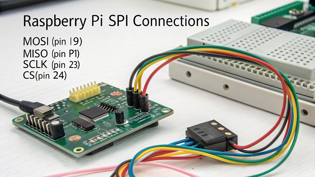
When connecting devices to your Raspberry Pi SPI bus, you’ll need to correctly identify the MOSI, MISO, SCLK, and appropriate CE pins on the GPIO header according to whether you’re using SPI0 (GPIO 7-11) or SPI1 (GPIO 16-21).
You can connect multiple SPI devices simultaneously by assigning each device a unique chip select line, with SPI0 offering CE0 (GPIO 8) and CE1 (GPIO 7) for device addressing.
For proper signal integrity, keep wire connections as short as practical and consider using a Pi Wedge adapter for clearer pin identification during your prototyping phase.
While SPI0 is the standard interface, advanced configurations allow devices to be wired with daisy-chained connections sharing the same MOSI and MISO lines.
Remember that the Raspberry Pi SPI bus interface requires additional configuration as it’s disabled by default on Raspberry Pi systems, so you’ll need to enable it through raspi-config before use.
The Raspberry Pi Zero 2 W is particularly well-suited for compact SPI projects due to its integrated wireless capabilities while maintaining the same GPIO pinout as larger models.
Pin Layout Essentials
Proper pin identification forms the foundation of successful SPI implementation on your Raspberry Pi system. SPI0 primarily utilizes GPIO pins 7-11, with default chip-select pins CE0 (GPIO 8) and CE1 (GPIO 7).
For expanded capabilities, SPI1 leverages GPIO pins 16-21, requiring dtoverlay command activation.
When implementing pin identification methods, connect the four essential wires—MOSI, MISO, SCK, and CS—to their corresponding pins on both your Raspberry Pi and peripheral device.
Maintain voltage compatibility between components to prevent damage. Key wiring considerations include minimizing wire length to reduce signal degradation and utilizing breakout boards for multi-device setups. For accurate pin connections, consider using Pinout.xyz resources which provide detailed diagrams maintained by the community.
The latest Pi 5 model delivers substantially more processing power at 2.4GHz, enabling more complex SPI communication projects with improved performance.
For Pico implementations, leverage the microcontroller’s flexible pin configurations by specifying desired connections during initialization, offering greater design freedom than traditional Raspberry Pi boards. The H suffix models offer pre-soldered GPIO header pins that simplify connectivity for beginners working with SPI interfaces.
Before connecting any devices to your Raspberry Pi, ensure you have properly written the operating system image to your microSD card using Raspberry Pi Imager.
Multiple Device Connection
Connecting multiple devices to your Raspberry Pi SPI bus expands its input/output capabilities while maintaining efficient communication through a single interface. The core principle relies on proper SPI device selection through dedicated Chip Select (CS) lines, preventing bus contention management issues when devices attempt simultaneous communication. The Raspberry Pi offers a total of five CE lines across its two SPI buses for connecting multiple devices. The RP2040 microcontroller features two SPI channels that can each define only one set of pins for SPI signals. When troubleshooting connection issues, implementing formative feedback tools can help identify specific wiring problems with your SPI configuration.
| Connection Component | Implementation Strategy |
|---|---|
| MOSI, MISO, SCLK | Shared among all devices |
| CS Lines | Unique GPIO per device |
| Bus Contention | Tri-state MISO when inactive |
| Manual CS Control | Software GPIO toggling |
| Multi-device Sync | Sequential device activation |
When implementing your multi-device configuration, connect all MOSI, MISO, and SCLK lines in parallel across devices. Assign unique GPIO pins for each device’s CS line. Your software must explicitly manage GPIO pin usage, driving the appropriate CS low before transmission and high afterward to maintain proper multi-device synchronization.
Python Programming With the SPI Bus
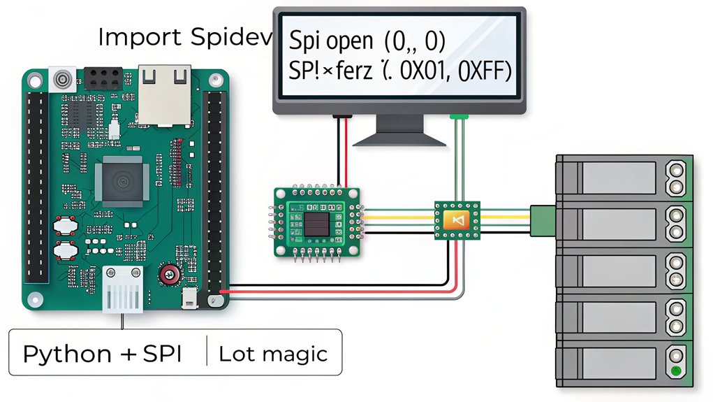
Python offers a straightforward approach to SPI communication on the Raspberry Pi through the spidev module, which provides essential functionality for interfacing with SPI devices.
You’ll need root privileges to initialize this Python library for peripheral communication.
Begin by creating an SPI object with spidevSpiDev(), then open communication by specifying your bus and chip select numbers. Device initialization requires configuring speed parameters through max_speed_hz to match your hardware’s capabilities.
For data transactions, utilize xfer2) to maintain chip select assertion throughout the entire operation. Remember that SPI operates in full duplex mode—each byte you transmit simultaneously returns a response byte.
When constructing your transactions, arrange data in byte lists that conform to your device’s protocol specifications. Proper speed configuration guarantees reliable data exchange while leveraging SPI programming principles for efficient hardware integration.
This communication protocol is particularly useful when interfacing with components like the Microchip MCP3002 ADC that can measure analog voltages for sensors in your Raspberry Pi projects.
The MCP23S08 GPIO expander can be programmed using Python to control LEDs and read button states through register operations.
Practical Projects Using SPI Peripherals
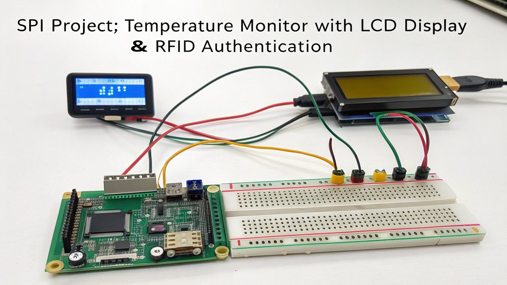
You’ll discover practical utility of the Raspberry Pi SPI bus when implementing a Temperature Monitor project that utilizes MAX6675 sensors for high-speed data acquisition at precise sampling intervals.
Your second project option integrates Digital Displays using SPI-driven OLED or TFT modules, requiring minimal GPIO pins while enabling rapid screen refreshes.
These implementations demonstrate SPI’s advantages in real-time data collection and visualization applications, maximizing the Raspberry Pi’s I/O capabilities through efficient peripheral management. The full duplex communication capability of SPI ensures simultaneous data transmission and reception, optimizing performance in time-sensitive projects. SPI can effectively interface with multiple devices on the same bus through unique chip select lines, allowing you to expand your project capabilities without exhausting available GPIO pins. For more advanced applications, consider integrating SPI with a home automation system to control smart lighting and temperature sensors simultaneously. Similar to the retro gaming console project with RetroPie, SPI interfaces can handle the quick response times needed for interactive applications.
Project 1: Temperature Monitor
When implementing a temperature monitoring system with your Raspberry Pi, it’s important to understand that while SPI offers excellent communication speeds, the popular DS18B20 temperature sensor actually utilizes a one-wire protocol rather than SPI. This protocol enables multiple temperature sensors to share a single GPIO pin efficiently.
For SPI-based projects, you’ll need to enable the interface in your Raspberry Pi configuration. Write Python scripts utilizing the SpiDev library for SPI peripherals, while DS18B20 sensors require one-wire library implementation. Temperature readings can be obtained in both Fahrenheit and Celsius through proper Python code implementation.
Your data logging system can be programmed to record temperature readings at specified intervals, with button-controlled functions to manage monitoring sessions. Using LEDs connected to GPIO pins provides visual status indicators that help users monitor system operation without requiring terminal access.
Power efficiency considerations are critical for long-term deployment. Integrate proper circuit setup with pull-up resistors to guarantee accurate temperature readings within ±0.5°C precision. Consider installing Node.js environment for creating web interfaces that can display your temperature data remotely.
Project 2: Digital Display Integration
Digital display integration represents a common application for SPI peripherals in Raspberry Pi projects.
When implementing such a system, you’ll need to select from various display types: TFT LCDs offer high resolution, OLEDs provide superior contrast, while E-ink displays excel in power efficiency.
Begin by enabling SPI through raspi-config, then connect your chosen display to the Pi’s SPI pins (MOSI, MISO, SCLK, CS).
Install relevant libraries—spidev or Luma for OLEDs—to handle the communication protocol. Configuring the display properly requires connecting the Chip Select pin to GPIO 24 for reliable communication.
For Sainsmart displays specifically, you may need to rewire GPIO pins with DC connected to GPIO24 and RES to GPIO25 to resolve flickering issues.
Effective power management requires consideration of display consumption characteristics; OLEDs draw less current than backlit LCDs.
Implement sleep modes and brightness controls to enhance battery life in portable applications.
For peak performance, configure proper timing parameters and manage the frame buffer efficiently to prevent display artifacts and guarantee responsive visualization.
Troubleshooting Common SPI Connection Issues
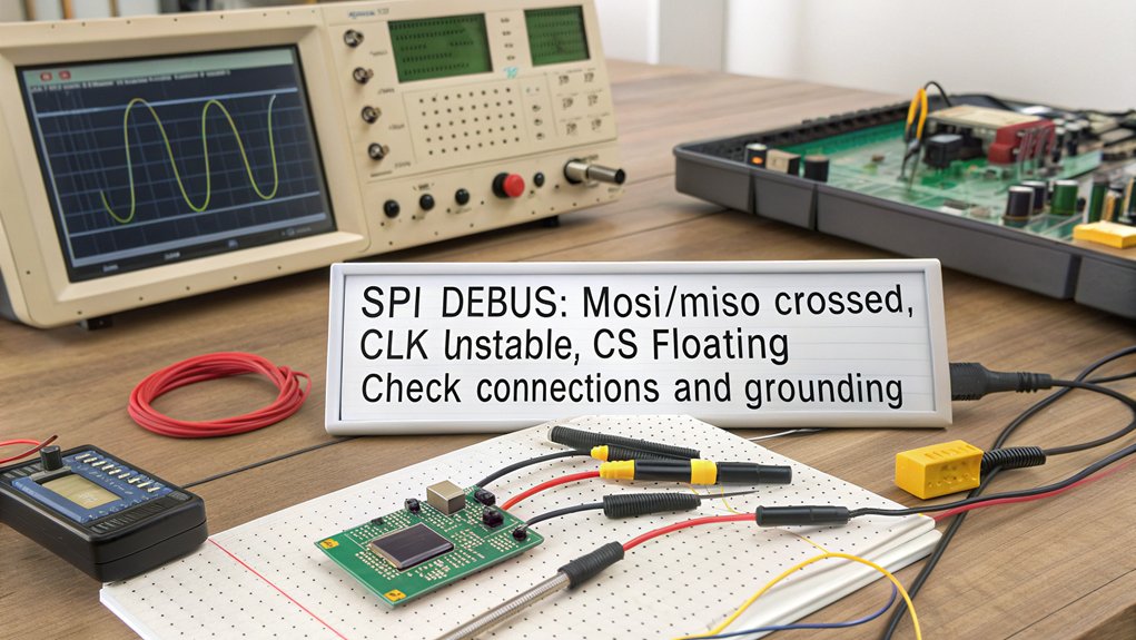
Connecting to the SPI bus may sometimes result in unexpected behavior or failures that require methodical troubleshooting to resolve. When confronted with SPI communication issues, first verify initialization by checking if SPI is enabled in `/boot/config.txt` and properly loaded in the device tree. Consider monitoring login attempts to identify potential security threats that might affect your SPI connection.
Common connection mistakes include incorrect CPOL/CPHA mode selection and improper chip select configuration. Remember to always specify the max_speed_hz parameter when using spidev to avoid communication issues with high-frequency signals. Be aware that SPI1 bus limitations may prevent certain mode configurations, as some auxiliary SPI buses only support modes 0 and 2.
For signal-related SPI troubleshooting tips, deploy an oscilloscope to validate SCK, MOSI, and chip select signals. Confirm your configuration doesn’t contain erroneous characters and matches your device’s specifications. After modifications, always reboot your Pi.
Software issues frequently stem from improper Python implementation of the `spidev` module or inadequate error handling. Verify physical connections are secure and that your power supply remains stable throughout communication cycles.
Frequently Asked Questions
Can SPI and I2C Be Used Simultaneously on Raspberry Pi?
Yes, you can utilize SPI-I2C compatibility for simultaneous device communication on your Raspberry Pi. These protocols operate independently through separate GPIO pins, enabling concurrent access to multiple peripherals with proper configuration.
How Does SPI Performance Compare to Other Communication Protocols?
SPI offers blindingly fast data transfer compared to I2C and UART, reaching 100+ Mbps. Your advantages include full-duplex operation and higher throughput, while disadvantages encompass higher pin count and potential latency for short transmissions.
What Is the Maximum Clock Speed on the Raspberry Pi SBI Bus?
Your maximum clock is theoretically 125MHz (core_freq/2), but you’ll encounter SPI limitations from capacitance and signal integrity. Practical implementations typically achieve 30-75MHz depending on peripheral and circuit design.
Can Multiple Raspberry Pi SPI Buses Be Configured on One Raspberry Pi?
Yes, you can configure multiple SPI buses on your Pi through device tree overlays. SPI bus limitations vary by model, with Pi 4 supporting up to 6 SPI controllers, constrained by available GPIO pins.
How Do You Handle Voltage Level Differences Between SPI Devices?
Properly protect potential problems when pairing peripherals. You’ll need level shifters for interfacing devices with incompatible voltages. Voltage dividers work for downshifting 5V to 3.3V, while dedicated ICs provide bidirectional conversion with ideal signal integrity.
What Did We Learn About the Raspberry Pi SPI Bus?
By mastering the Raspberry Pi SPI bus, you’ve revealed a communication protocol that functions like a well-orchestrated symphony of data transfer. You’ve configured the hardware interface, established proper electrical connections, and implemented Python code to facilitate bidirectional data exchange. When troubleshooting, systematically verify signal integrity with an oscilloscope, validate chip select functionality, and guarantee clock frequency compatibility between master and peripheral devices.

I am a retired software engineer with experience in a multitude of areas including managing AWS and VMWare development environments. I bought a relative a mini-PC a year ago and have become passionate about the technology and its potential to change how we deploy software.