You’re about to discover how SPI communication on a Raspberry Pi can expand your device’s capabilities for interfacing with sensors, displays, and memory devices. This serial protocol offers faster data transfer than I2C while requiring minimal GPIO pins. Whether you’re building a weather station, custom display interface, or data acquisition system, mastering SPI will reveal new project possibilities. The process isn’t complicated, but requires attention to detail in both hardware connections and software configuration.
Key Takeaways
- Enable SPI by running `sudo raspi-config`, navigating to Interface Options, selecting SPI, and rebooting.
- Connect peripheral devices by wiring MOSI to GPIO10, MISO to GPIO9, SCLK to GPIO11, and CS to GPIO8.
- Install required libraries with `sudo apt-get install python3-spidev` for Python programming.
- Initialize SPI communication with `spi = spidev.SpiDev(); spi.open(0,0); spi.max_speed_hz = 1000000`.
- Configure appropriate mode settings (0-3) and transfer data using the `spi.xfer2()` function.
What Is SPI and Why Use It on Raspberry Pi
When exploring communication protocols for your Raspberry Pi projects, SPI stands as one of the most versatile options available. This Serial Peripheral Interface follows a master-slave architecture where your Pi (the master) controls communication with peripheral devices like sensors, displays, and memory chips.
Understanding SPI basics involves recognizing its four key signals: MOSI, MISO, SCLK, and SS. This synchronous protocol enables full-duplex communication, allowing simultaneous data exchange between devices. SPI typically supports various word size options such as 8, 12, or 16 bits through shift registers in both the master and slave devices.
SPI advantages include high-speed data transfer, shorter distances between components, and multidrop capabilities for connecting multiple slaves. The protocol supports differentiation between multiple devices on the same bus through unique chip select lines.
You’ll find SPI particularly useful when interfacing with SD cards, LCD screens, or analog-to-digital converters. Similar to how mini PCs use PCIe slots for external GPU connections, SPI provides essential expansion capabilities for your Raspberry Pi projects. Its wide implementation across embedded platforms makes it invaluable for innovative projects requiring reliable, fast communication.
Hardware Requirements for SPI Communication
| Component | Purpose |
|---|---|
| Raspberry Pi | Processing unit with SPI capability |
| Jumper wires | For Wiring Techniques and connections |
| SPI peripherals | Sensors, memory devices, or microcontrollers |
| Breadboard | For prototyping and testing connections |
Ensure Device Compatibility by verifying voltage levels and pin configurations before connecting peripherals. Keep wires short and organize them by color to maintain Signal Integrity and prevent data corruption. For complex setups, consider using additional hardware chip selects to manage multiple devices efficiently. The Raspberry Pi supports communication with multiple SPI devices using chip select pins that allow a single SPI master to control several peripheral devices. The Raspberry Pi 3 specifically provides two CE lines for connecting SPI slaves without requiring additional decoder chips.
Enabling the SPI Interface in Raspberry Pi OS
The Raspberry Pi’s SPI interface remains dormant by default in Raspberry Pi OS, requiring explicit activation before you can establish hardware connections. You have two straightforward methods to activate this powerful interface.
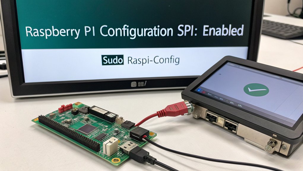
Method 1: Use the terminal command `sudo raspi-config`, navigate to “Interfacing Options,” select “P4 SPI,” and choose “Yes” to enable it.
Method 2: From the desktop, access “Preferences > Raspberry Pi Configuration” and enable SPI through the graphical interface.
After activating interfaces through either method, always reboot your system with `sudo reboot`. Using Raspberry Pi Imager can streamline the initial setup process, allowing you to configure various settings before booting your device for the first time. Before enabling SPI, it’s recommended to check SPI status using the ls /dev/spi command to verify if it’s already activated.
Verifying configurations is essential—use `lsmod | grep spi` to confirm the presence of spi-bcm2835 module or run `ls /dev/spi*` to check for available SPI devices. This guarantees your system is properly configured for SPI communication. Alternatively, you can enable SPI directly from the command line using dtparam spi=on for quicker configuration. Make sure you’re using a Class 10 UHS-I SD card for optimal performance with your SPI applications.
Understanding SPI Pin Connections and Wiring
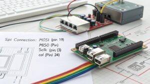
To connect SPI devices to your Raspberry Pi, you’ll need to identify the correct pin connections for MOSI, MISO, SCK, and CS signals.
You must wire your peripheral device’s MOSI to the Pi’s MOSI pin, MISO to MISO, SCK to SCK, and select an appropriate CS pin for each unique device.
Proper grounding and consistent power supply levels between devices are essential for reliable SPI communication. When identifying pins, remember that GPIO numbers correspond to the BCM numbering scheme used in programming. For the most accurate pinout information, you can refer to Pinout.xyz, a community-driven platform that provides detailed diagrams of Raspberry Pi connections.
Pin Connections Basics
Establishing proper connections between your Raspberry Pi and SPI devices requires understanding the four essential SPI pins and their functions.
These pins form the foundation of the SPI pinout overview and enable efficient chip select management when connecting multiple devices.
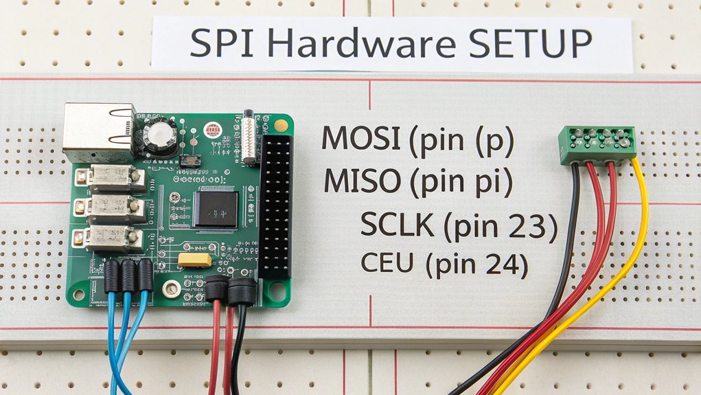
- SCLK (GPIO 11): The clock signal generated by the master that synchronizes data transmission between devices
- MOSI (GPIO 10): Master Out Slave In line that transmits data from your Raspberry Pi to the connected SPI device
- MISO (GPIO 9): Master In Slave Out line that receives data from the SPI device back to your Raspberry Pi
- CS/CE (GPIO 7-8): Chip Select pins that activate specific devices when multiple peripherals share the same SPI bus
The Pi Wedge breakout board provides convenient access to these SPI signals for easier breadboard prototyping and peripheral connections.
For SPI0, utilize GPIO pins 7-11, while SPI1 requires configuration through dt-overlays and uses GPIO 16-21. Remember that in MicroPython, default pins are already configured with SPI0_SCK on Pin 6, SPI0_MOSI on Pin 7, and SPI0_MISO on Pin 4.
Device Wiring Guide
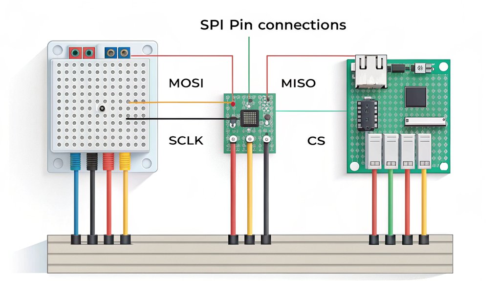
Properly connecting your SPI devices to a Raspberry Pi involves understanding both the fundamental pinout arrangements and specific wiring considerations for reliable communication.
For basic setups, connect all devices’ MOSI, MISO, and SCLK lines to GPIO 10, 9, and 11 respectively (for SPI0). Each device requires its own CS/CE line—typically GPIO 8 (CE0) and GPIO 7 (CE1).
For more than two devices, utilize additional GPIO pins as chip select outputs or enable SPI1 through dtoverlay configurations. Using the command `dtoverlay=spi1-1cs` in the `/boot/firmware/config.txt` file will enable a second SPI interface.
Device compatibility considerations should include operating voltage and logic levels. Maintain short connections to minimize signal degradation at higher clock speeds.
Wiring best practices dictate proper grounding between all components, physical separation from power lines, and systematic labeling of connections for troubleshooting. Remember to select the appropriate numbering system when referencing GPIO pins in your code. For creative projects, you can design LED patterns that change based on data received through your SPI connection.
Always confirm your connections before powering up to prevent hardware damage.
Installing SPI Libraries and Dependencies
Before diving into SPI communications on your Raspberry Pi, you’ll need to set up the appropriate libraries and dependencies. The kernel’s built-in spidev driver provides foundational support, but additional libraries enhance functionality for different programming languages.
Setting up SPI on Raspberry Pi requires proper dependencies alongside the kernel’s spidev driver to maximize functionality across programming environments.
- Enable SPI Interface – Use `raspi-config` or add `dtparam=spi=on` to `/boot/config.txt`, then reboot to create `/dev/spidevN.N` device files.
- Install WiringPi – Clone the repository, execute `./build`, and verify installation with `gpio -v` for C/C++ development.
- Configure Node.js – Install the asynchronous `pi-spi` library via npm (`npm install pi-spi`), noting that sudo privileges may be required.
- Python Integration – Set up Python wrappers by installing `python-setuptools` and `python-dev` packages for SPI access through Python scripts. The spidev driver is supported on all Raspberry Pi models and works with many other compatible boards as well. Maintaining regular system updates is crucial for compatibility with SPI drivers since original OS builds may lack necessary hardware support. When setting up SPI on the Raspberry Pi 5, you’ll benefit from its dual-band Wi-Fi capabilities for networking during your development process.
Programming SPI Communication With Python
To program SPI communication on your Raspberry Pi, you’ll need to utilize the spidev library which provides a Python interface for interacting with SPI devices.
You can initialize an SPI connection with `spi = spidev.SpiDev(0, 0)` and configure essential parameters like speed with `spi.max_speed_hz = 1000000`.
Writing device interfaces typically involves crafting byte sequences according to the peripheral’s datasheet specifications and transferring them using the `spi.xfer2()` method which handles the bidirectional communication. When setting up SPI communication with a device like an FPGA, you’ll need to configure specific mode settings such as clock polarity and phase to match your peripheral’s requirements. For controlling devices like the MCP23S08, you’ll need to access specific address registers to configure pins as inputs or outputs.
Using the Spidev Library
Once you’ve enabled SPI on your Raspberry Pi and installed the Spidev library, you can begin programming SPI communication in Python.
The spidev installation provides a clean API for interfacing with SPI devices through simple function calls.
For effective spidev usage, follow these steps:
- Import the library with `import spidev` at the beginning of your script.
- Initialize your SPI connection using `spi = spidev.SpiDev()` and then `spi.open(0,0)` to open bus 0, device 0.
- Configure essential parameters like `spi.max_speed_hz=1000000` and `spi.mode = 0` to match your device specifications.
- Implement data transfers using `spi.xfer2([bytes])` for simultaneous transmission and reception, and always `spi.close()` when finished.
This setup allows you to interface with analog components like the MCP3002 ADC which enables analog voltage measurement on Raspberry Pi.
If you encounter permission denied errors, use sudo chmod 666 on your SPI device file to grant access without requiring superuser privileges.
Writing Simple Device Interfaces
After mastering the Spidev library basics, you’ll want to create practical interfaces for specific SPI devices in your Python projects.
Start by implementing device-specific SPI protocols that handle the required communication sequence—including start bits, data bits, and stop bits.
Robust error handling is essential for reliable operation. Implement checksums or CRC mechanisms to verify data integrity during transmission.
When designing your interfaces, account for the device’s specific SPI mode (0-3) and appropriate clock speed, typically under 1MHz for most applications. Remember that proper master-slave configuration is critical for successful data transfer.
Take advantage of SPI’s full duplex capability when designing your communication protocol, as this allows for simultaneous data transmission and reception without additional overhead.
Consider threading for concurrent operations when interfacing with multiple devices. This prevents data corruption and improves response time.
Your interface should abstract the low-level details, providing clean methods that execute the necessary SPI transactions while handling potential transmission errors automatically.
For security-critical applications, implement TLS encryption to protect data transmitted over SPI connections from potential interception or tampering.
Ensure you use NodeSource repository for installing Node.js to guarantee compatibility with your SPI communication code when integrating with JavaScript applications.
Implementing SPI Device Control With Sample Code
Translating SPI theory into practical implementation requires writing code that properly initializes, configures, and communicates with SPI devices.
Your Python implementation should focus on clear device initialization and proper chip selection to guarantee data integrity across the SPI bus.
- Initialize the SPI interface: Import spidev library, create an SPI object with `spi = spidev.SpiDev()`, then open the appropriate bus with `spi.open(0, 0)` for CE0.
- Configure communication parameters: Set `spi.max_speed_hz = 1000000` and `spi.mode = 0` to match your device requirements.
- Transfer data: Use `response = spi.xfer2([command_byte, data_byte])` to send commands and receive responses in a single clock-synchronized transaction. The documentation in the raspberrypi/documentation repository provides valuable examples and best practices for SPI implementation.
- Close properly: End with `spi.close()` to release resources when communication is complete.
Before implementing SPI communication, ensure your Raspberry Pi has a stable internet connection for downloading any necessary libraries like spidev that aren’t included by default.
Remember that Raspbian supports dual-band wireless networking which can provide more reliable connections for downloading development packages and tools.
Troubleshooting Common SPI Connection Issues
Despite well-designed SPI implementation code, you’ll inevitably encounter communication issues that require methodical troubleshooting. Start by verifying kernel module loading with `ls /dev/spidev*` and checking if SPI is enabled through `raspi-config`.
Common issues include incorrect wiring—confirm MOSI, MISO, SCLK, and CS connections using the proper BCM pin numbering.
Double-check your SPI wiring—proper MOSI, MISO, SCLK, and CS connections with BCM pin numbering are essential for successful communication.
Test signal integrity with a simple loopback by connecting MOSI to MISO, which should return transmitted data. Guarantee stable power supply, particularly when peripherals draw significant current.
Address library compatibility by updating Python’s `spidev` package and verify mode settings match your device’s requirements. Implement robust error handling to catch communication failures.
Remember that logic level mismatches between 3.3V Pi and 5V peripherals require level shifters to prevent hardware damage and guarantee reliable communication. For network-connected Raspberry Pi projects, ensure you’re using SSH key authentication rather than password-based login to enhance your device’s security.
Consider organizing collaborative troubleshooting sessions where students can share their experiences and work together to solve complex SPI connectivity problems.
Try Using SPI Communication on a Raspberry Pi On Your Next Project!
You’ve now mastered SPI implementation on your Raspberry Pi. Like a well-orchestrated symphony, your microcontroller and peripherals can communicate seamlessly using the four-wire interface. Remember to properly close SPI connections in your code, verify your wiring connections, and consult the device datasheets for specific timing requirements. With these skills, you’re equipped to integrate sensors, displays, and other SPI devices into your projects.
Frequently Asked Questions
Can I Connect Multiple SPI Devices to a Single Raspberry Pi?
Yes, you can connect multiple SPI devices to your Raspberry Pi through a shared bus. Each device needs unique addressing via separate chip select lines, enabling efficient multiple connections simultaneously.
How Does SPI Performance Compare to I2C for Sensor Applications?
Like a sports car versus a bus, SPI’s superior speed advantages deliver markedly higher sensor data throughput than I2C—you’ll experience multi-MHz rates and full-duplex operation, critical for high-frequency sampling applications.
What Power Considerations Exist When Using SPI With 3.3v/5v Devices?
When connecting 3.3V and 5V devices via SPI, you’ll need proper voltage level management. Implement level shifting circuits to prevent damage and guarantee reliable data transmission between components with different voltage requirements.
Can SPI Communication Work Reliably Over Longer Cable Distances?
Imagine signals fading into the ether. You’ll find SPI struggles beyond 20cm at high speeds. Cable length severely impacts signal integrity. Employ proper shielding techniques and noise reduction methods for marginally better results.
How Do I Debug Timing Issues Between SPI Master and Slave Devices?
Debug SPI timing issues by using oscilloscope timing analysis to observe signal integrity. Verify clock polarity/phase settings match between devices. Reduce clock frequency to guarantee reliable data capture at both ends.

I am a retired software engineer with experience in a multitude of areas including managing AWS and VMWare development environments. I bought a relative a mini-PC a year ago and have become passionate about the technology and its potential to change how we deploy software.