
What do you do when SPI Communication Errors Happen?
When your Raspberry Pi displays nothing but timeout errors while attempting to communicate with your SPI-based temperature sensor, you’re facing a common yet frustrating challenge. You’ve enabled SPI in raspi-config, double-checked your wiring, and your code seems correct—yet the communication fails. Beyond the obvious hardware checks, you’ll need to investigate kernel-level configurations, signal integrity issues, and potential clock timing problems that might be preventing successful data exchange between your Pi and peripheral devices.
Key Takeaways
- Verify SPI is enabled using `sudo raspi-config` and check for device nodes in `/dev/spidev*` after rebooting.
- Confirm physical connections are correct with proper MOSI/MISO wiring and unique chip select lines for each device.
- Use `lsmod | grep spi*` to check loaded modules and `dmesg | grep spi` to inspect kernel logs for errors.
- Test signal integrity with a multimeter or oscilloscope, checking for interference, crosstalk, and proper voltage levels.
- Adjust SPI clock speed based on device specifications and use shielded cables with proper grounding.
Understanding SPI Fundamentals on Raspberry Pi
When troubleshooting SPI communication errors on Raspberry Pi, you’ll need a solid understanding of how the protocol works.
SPI basics include four essential lines: SCLK (clock), MOSI (master output), MISO (master input), and SS/CS (slave select).
The protocol operates in a master-slave architecture where your Pi typically acts as the master, controlling the communication flow.
Clock synchronization is critical – all data transfers are synchronized to the SCLK signal generated by the master device. This makes SPI a fully synchronous protocol capable of full-duplex operation.
Your Raspberry Pi can communicate with multiple slave devices, but each requires its own dedicated SS/CS line.
This architectural feature enables high-speed data transfer that’s perfect for interfacing with sensors, displays, and memory devices where real-time communication is essential. For ADC applications, the MCP3008 can read up to 8 analog channels and provide digital output through the SPI interface. Remember to load the SPI kernel module with gpio load spi command before attempting to run your SPI programs.
To properly work with SPI communication, it’s important to select the correct pin numbering system when configuring your GPIO pins in your code.
Before attempting any SPI communication, it’s advisable to run ‘sudo apt update’ and ‘sudo apt upgrade’ to ensure your Raspberry Pi OS has all the latest package information and updates.
Enabling and Configuring SPI Interfaces
Before you can utilize SPI communication on your Raspberry Pi, you’ll need to explicitly enable it since this interface is disabled by default in the kernel. Configuring SPI properly is essential for successful hardware communication with sensors and peripherals. For advanced configuration options, remember that pressing CTRL + SHIFT + X reveals additional customization features in Raspberry Pi Imager.
To enable SPI on your Raspberry Pi:
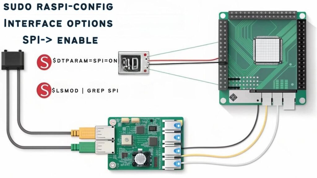
- Execute `sudo raspi-config` in your terminal to access the configuration utility
- Navigate to “5 Interfacing Options” followed by “P4 SPI” and select “Yes” to enable
- Reboot your device for the changes to take effect
- Verify successful enabling SPI by running `lsmod | grep spi` which should display the `spi-bcm2835` module
After rebooting, check for the presence of SPI device nodes in `/dev/spidev*`. You can use the `gpio readall` command to verify if the pin configuration is correctly set for SPI communication. Remember to keep your system updated for ideal driver compatibility. When enabled, the SPI interface will auto-load kernel module at boot time without requiring manual configuration.
Common SPI Driver and Kernel Issues

Despite proper configuration, SPI communication error on Raspberry Pi can occur due to various driver and kernel-related issues that often puzzle even experienced developers.
Kernel version incompatibilities frequently manifest when your SPI devices don’t appear in `/dev/spidev*`, especially after system upgrades. The root cause often lies in missing MDEV configurations or improper device tree support.
SPI driver compatibility varies greatly between Raspberry Pi models, with the RPi5 requiring different approaches than older versions. To troubleshoot these issues, consider accessing the command line through SSH connections for remote diagnostics without needing a display. Implementing firewall rules can help protect SPI communications when accessing your Pi remotely.
When troubleshooting, check kernel logs for specific SPI errors and verify boot parameters include `dtparam=spi=on`.
Custom-built kernels introduce additional kernel configuration challenges, particularly when essential driver directories are accidentally deleted during development. Starting over with a fresh pull from the git repository is often the best solution when this happens.
For performance-critical applications, you’ll need to decide between kernel-space drivers or user-space APIs based on your latency requirements. Significant driver improvements are expected in kernel version 4.1 with further enhancements in version 4.2 that may improve spidev performance.
Verifying Hardware Connections and Pin Assignments
Without proper hardware connections, SPI communication errors can occur on your Raspberry Pi.
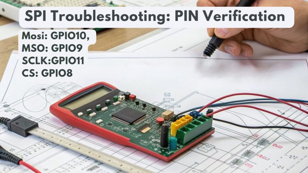
Begin your pin verification process by confirming GPIO assignments match your specific Pi model, as these can vary across versions. Verify MOSI and MISO lines aren’t reversed, which is a common oversight that prevents data transmission. For H suffix models, header pins are pre-soldered, making connections more straightforward than their non-H counterparts that require manual soldering. When working with e-ink displays, it’s essential to verify that your display has SPI interface compatibility with the Raspberry Pi. Using A2 cards can provide enhanced bus speeds and better command queueing for improved SPI performance. Consider using voltage dividers to ensure input voltage levels are scaled down to Pi-compatible standards.
- Use a multimeter to test continuity between your Pi’s SPI pins (GPIO 11, 10, 9, 8) and your device connections.
- Verify all grounds are properly connected to establish a common reference point.
- Check wiring integrity by examining for frayed cables, poor solder joints, or loose breadboard connections.
- Employ a logic analyzer to observe signal quality when persistent issues occur.
For multiple SPI devices, verify each has a unique chip select line to prevent communication conflicts.
Debugging SPI Communication Errors With System Tools
Once hardware connections are verified, system tools become your next line of defense in troubleshooting SPI communication issues on Raspberry Pi.
Command line utilities like `spincl` enable you to test and debug slave devices for SPI communication errors without developing custom software, saving valuable development time.
You’ll benefit from redirecting SPI transaction outputs to log files for offline analysis, helping identify timing and data discrepancies.
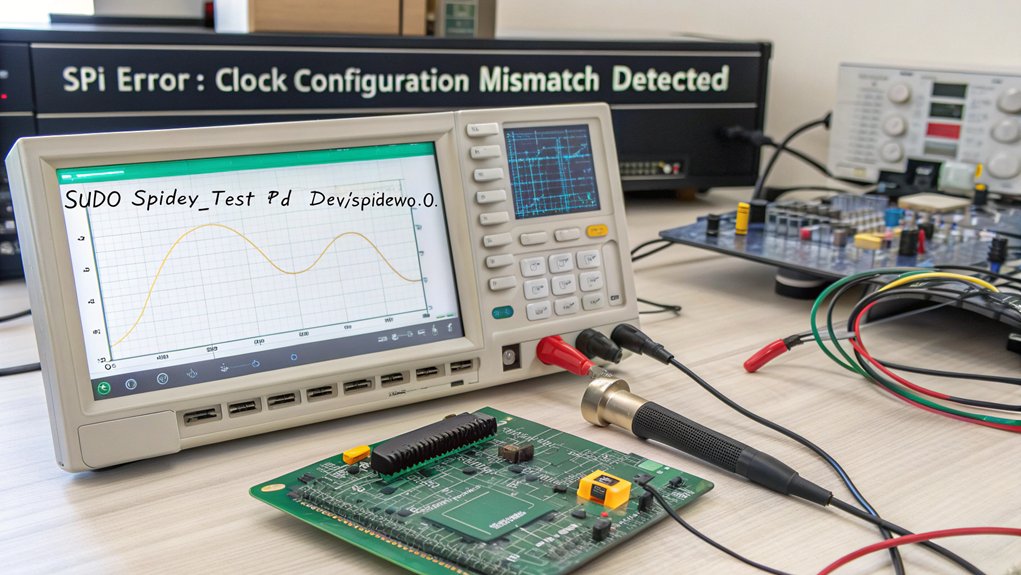
An oscilloscope remains essential for comparing expected signals with actual outputs, revealing protocol violations and signal integrity issues.
Consider implementing automated scripting with Python or bash to create repeatable test sequences.
These scripts can validate protocol timing, command responses, and data integrity through consistent batch runs.
This approach supports both interactive debugging and unattended testing scenarios, particularly valuable in CI environments where regression testing is critical.
The utility is GNU GPLv3 licensed and includes source code that can be freely downloaded for any modifications needed for your specific applications.
For more advanced debugging needs, connect the target device to a Debug Probe operating at a nominal 3.3V for precise signal monitoring and analysis.
Before proceeding with SPI troubleshooting, ensure you’ve verified Node.js installation with npm version check to rule out environment configuration issues.
Resolving Device-Specific SPI Communication Errors due to Compatibility Problems

When troubleshooting device-specific SPI compatibility problems, you’ll often encounter issues stemming from fundamental mismatches in device expectations rather than simple wiring errors.
Confirming proper device compatibility requires understanding each component’s specific requirements and configuration settings.
To resolve these problems effectively:
- Verify SPI mode compatibility – Match all connected devices to the correct mode (0-3) by consulting datasheets and adjusting your configuration settings accordingly.
- Address bus speed limitations – Set your SPI clock frequency to accommodate your slowest device to prevent data corruption.
- Update device drivers – Install the latest software drivers specifically designed for your hardware to guarantee peak communication.
- Test devices individually – Isolate and configure each device separately before attempting integration to identify specific compatibility issues.
Using CMSIS-DAP tools can significantly improve debugging capabilities when troubleshooting complex SPI issues on RP2040-based devices.
Consider utilizing the appropriate chip select pins on your Raspberry Pi to manage multiple SPI devices independently, as the standard SPI0 interface provides two chip selects (CE0 and CE1).
Proper pin configuration is essential, especially ensuring that MISO connects to MOSI between devices to establish direct connections for successful data transmission.
Use the chmod command to modify permissions for SPI device files if access is restricted during communication attempts.
Optimizing SPI Performance and Signal Integrity
Achieving ideal SPI performance on your Raspberry Pi requires careful attention to both clock synchronization and signal integrity factors. Configure your SPI clock speed based on both the Pi’s capabilities and your peripheral’s specifications. The SPI clock derives from the core clock divided by an even-numbered divisor, affecting overall throughput. For maximum efficiency, consider implementing larger data transfers rather than multiple smaller transactions. When using the MCP3008 ADC, set your clock to 2 MHz operation for reliable communication at 3.3V power levels. Similar to audio configurations, maintaining clean power supply is crucial for preventing interference in SPI communications.
| Optimization Area | Implementation Technique |
|---|---|
| Clock Synchronization | Set matching clock speeds; verify with oscilloscope |
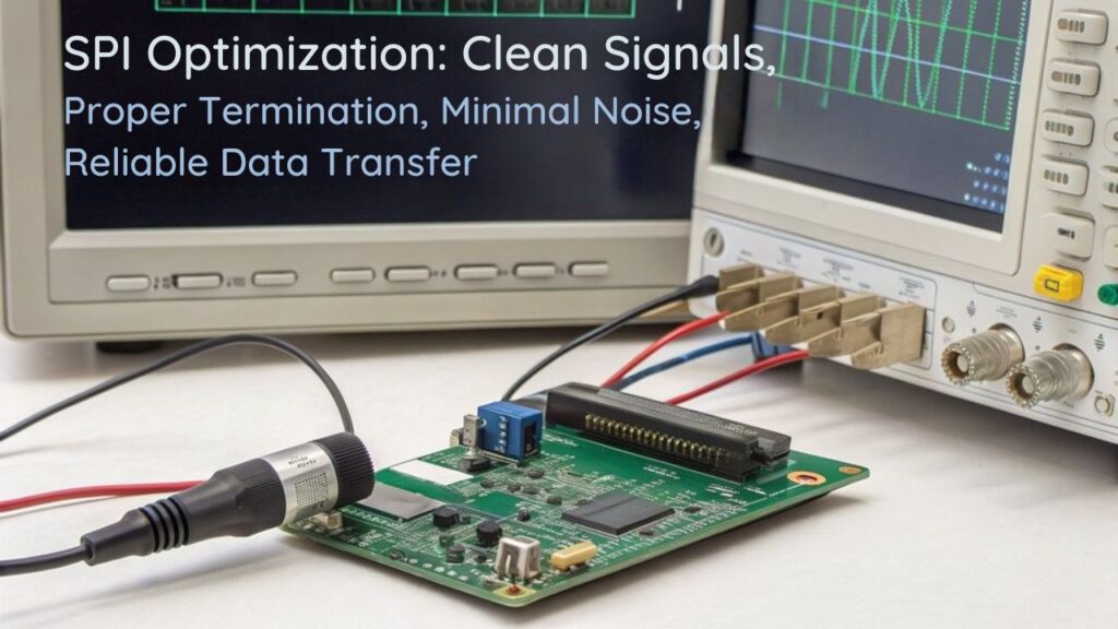
| Signal Optimization | Use short, shielded cables; proper grounding |
| Software Configuration | Update drivers; monitor system load |
For effective signal optimization, route SPI lines away from interference sources and implement appropriate pull-up/down resistors. Maintain stable voltage levels and consistent ambient temperatures to prevent data corruption. Regular testing with tools like `spidev_test` will help identify potential bottlenecks in your clock synchronization implementation.
Advanced SPI Troubleshooting Techniques

To diagnose persistent SPI communication issues on your Raspberry Pi, you’ll need to verify proper module loading with commands like `lsmod | grep spi` and check `/etc/modules` for the presence of spi-dev. You can analyze signal integrity by connecting an oscilloscope or logic analyzer to the SPI pins, observing waveforms for proper voltage levels, timing, and potential noise interference. Testing different configurations like 3-wire and 4-wire setups may help identify protocol-specific compatibility issues. Similar to how educators utilize formative feedback tools to guide students through coding challenges, methodical troubleshooting provides targeted insights into communication errors.
When standard troubleshooting fails, employ cross-device testing by connecting your SPI peripheral to another Raspberry Pi or microcontroller to determine if the problem originates from your device or the peripheral itself. Regular system updates can ensure you have the latest driver compatibility and bug fixes for SPI functionality. If all other methods fail to resolve the issue, consider the possibility of hardware failure affecting your SPI pins, as this rare but documented problem can cause persistent communication errors.
Signal Integrity Analysis
Signal integrity analysis forms the foundation of advanced SPI troubleshooting techniques when standard debugging methods fail to resolve persistent communication errors.
On Raspberry Pi, even seemingly functional SPI connections can suffer from subtle signal distortion or impedance mismatch issues that manifest as intermittent failures at higher speeds.
To properly diagnose these problems:
- Measure S-parameters across your SPI channel to identify reflections caused by trace discontinuities.
- Analyze eye diagrams to evaluate signal quality and determine maximum reliable clock rates.
- Use time-domain reflectometry (TDR) to pinpoint exact locations of impedance discontinuities.
- Evaluate crosstalk between adjacent SPI lines by measuring near-end and far-end coupling values.
Unlike protocols with strict impedance requirements, SPI tolerates various trace impedances (30-150Ω), but maintaining consistent impedance throughout signal paths remains critical for reliable high-speed operation. For electrically long SPI buses, placing series resistors close to the driver can effectively reduce crosstalk and improve signal quality. Properly configuring the clock polarity and phase settings is essential when troubleshooting communication issues between the Raspberry Pi master and peripheral slave devices.
Module Loading Verification
While signal integrity issues affect physical SPI communication characteristics, equally common failures stem from improper kernel module loading on the Raspberry Pi. Verify your SPI environment systematically using the following commands to identify module dependencies and kernel versioning conflicts. Device tree configuration is critical for proper hardware recognition between the Raspberry Pi and SPI peripherals. If your system properly loads the SPI drivers, it should expose two device files in the /dev directory for SPI communication. Raspbian’s APT package manager can be used to install any missing SPI-related dependencies for your project.
| Command | Purpose | Expected Result | |
|---|---|---|---|
| `lsmod \ | grep spi*` | Check loaded modules | `spidev` and `spi_bcm2835` present |
| `ls -l /dev/spi*` | Verify device nodes | `/dev/spidev0.0` or similar exists | |
| `modprobe spidev` | Manual load attempt | No errors returned | |
| `grep “spi=on” /boot/config.txt` | Confirm configuration | `dtparam=spi=on` found | |
| `dmesg \ | grep spi` | Check kernel messages | Successful SPI initialization logs |
When modules fail to load properly, check for kernel versioning mismatches between your SPI dependencies and the current system. For persistent configuration, add required modules to `/etc/modules`.
Cross-Device Testing Methods
When standard SPI troubleshooting fails to identify communication errors, cross-device testing becomes essential for isolating hardware from software issues.
Analyzing cross device compatibility requires systematic verification of both physical connections and communication protocols.
- Verify protocol alignment – Confirm SPI mode, clock phase/polarity settings match between your Pi and peripheral device specifications.
- Monitor real-time signals – Deploy a logic analyzer to observe handshake timing, data corruption, and protocol adherence during transmission.
- Test full-duplex operation – Validate simultaneous send/receive functionality by transmitting test patterns while capturing response data.
- Validate chip select behavior – Check that each device responds only to its designated CS line without interference from other connected devices.
These methods help pinpoint whether issues stem from hardware incompatibilities, timing problems, or software configuration mismatches across your SPI ecosystem.
For complex SPI issues with high-performance components, consider using the Raspberry Pi 5 which offers significant improvements in processing capabilities and interface stability.
Maintaining ergonomic posture during extended troubleshooting sessions can prevent fatigue that might otherwise lead to overlooked connection issues.
Frequently Asked Questions
Can I Use SPI and I2C Simultaneously on the Same Raspberry Pi?
Yes, you can use SPI and I2C simultaneously on your Raspberry Pi. These communication protocols operate on different GPIO pins with complete compatibility, offering distinct advantages for connecting multiple peripheral devices.
How Do SPI Clock Speeds Affect Communication With Different Device Types?
SPI clock speeds directly impact device compatibility. You’ll find some devices require specific speeds for reliable operation, while others tolerate wider ranges. Always match clock rates to your device’s specifications.
Will SPI Work Reliably Through Level Shifters With 3.3v/5v Devices?
Properly implemented level shifters guarantee 99% reliability. You’ll need appropriate level shifting techniques like 74HCT or 74LVC2T45 components to overcome voltage compatibility issues when connecting 3.3V and 5V SPI devices.
What’s the Maximum Cable Length for Stable SPI Communication?
You’ll achieve reliable SPI connections within 2-3 meters maximum. Maintain signal integrity by using proper cable shielding, reducing clock speed below 1MHz, and employing twisted-pair cables for longer runs.
Can Multiple Python Libraries Access the SPI Bus Without Conflicts?
Yes, you can have multiple Python libraries access the SPI bus without conflicts if you implement proper shared bus management and guarantee careful CS pin control for concurrent device access.
Conclusion
Like a stubborn lock that only opens with the right key combination, your SPI communication issues can be solved with methodical troubleshooting. You’ve now got the complete toolkit—from verifying hardware connections to analyzing signals with logic analyzers. Remember, it’s the details that matter: proper GPIO assignments, clean power supplies, and precise timing parameters will transform your frustrating SPI errors into reliable data transmission across your Raspberry Pi projects.

I am a retired software engineer with experience in a multitude of areas including managing AWS and VMWare development environments. I bought a relative a mini-PC a year ago and have become passionate about the technology and its potential to change how we deploy software.